A Modular Keypad Needs More Than Magnets
A hand-wired keypad prototype examined through mechanical fit, signal acquisition and the meaning of detachable input.
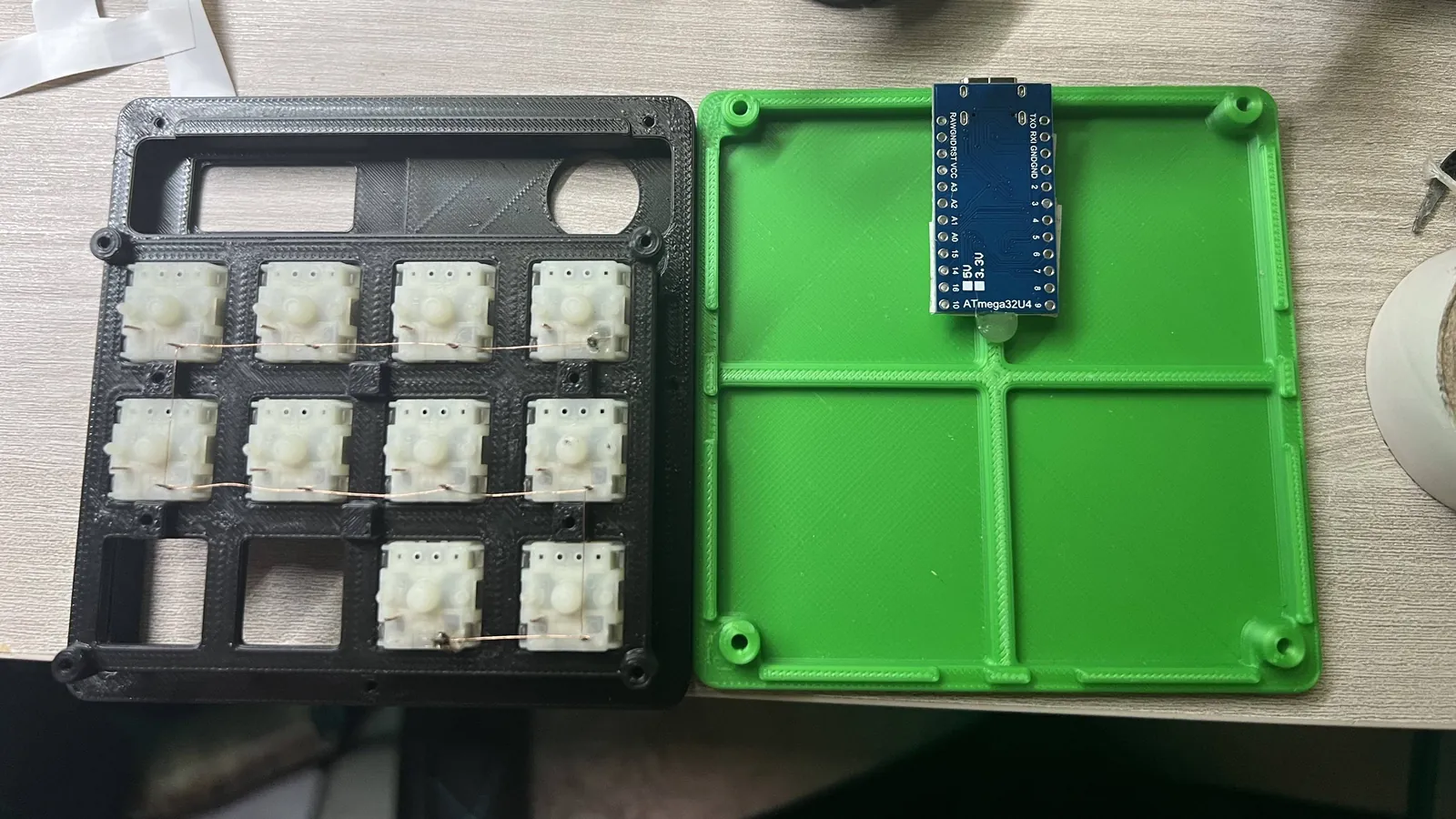
My keypad had room for twelve switches and contained ten. That small discrepancy captures the project fairly well: I was building a personal prototype around components I already owned, rather than manufacturing a finished product from an unconstrained specification.
The main unit combined mechanical switches, a rotary encoder, an OLED display and LED lighting. A detachable extension held four potentiometers. I designed and printed the PLA enclosure, mounted the components and wired them by hand. The symmetric magnetic arrangement let the extension attach in different physical orientations. The proof of concept worked, while assembly exposed tight wiring space, an undersized rotary-control opening and awkward LED positioning.
The project record includes assembly photographs. At that revision, the tracked repository contains a README rather than firmware, schematics or CAD files. It supports a retrospective on the prototype, not a reproducible performance claim. The remaining engineering question is what must stay true when a physical control becomes part of a larger input device.
A reliable modular keypad has to preserve meaning across several boundaries. A switch must become a stable state; rotation must become movement in the correct direction; a module's orientation must preserve its electrical mapping; and its disappearance must not leave the computer acting on an input that no longer exists.
 Assembly photograph from the project record. Ten switches occupy the twelve-position frame; the controller board sits in the base. Photo: Daniel Buttigieg
The small prototype made direct wiring reasonable
I connected the switches individually rather than building a scanning matrix. For ten installed switches, that kept the topology straightforward: each input could be associated with one switch. It also consumed one input per switch, before accounting for the encoder, analog controls, display and lighting.
A matrix changes that trade-off. Twelve positions arranged electrically as three rows and four columns require seven row-and-column lines instead of twelve individual inputs. The controller selects one part of the grid and reads the other. This saves pins by reusing conductors, but the shared paths can make several simultaneous closures ambiguous.
In the QMK matrix explanation, three closed switches occupy three corners of a two-by-two grid. During scanning, a signal can travel through those closed switches and make the unpressed fourth corner appear connected. Appropriately oriented diodes block the unwanted reverse path. That problem comes from the circuit topology, not from the choice between soldering wires and ordering a PCB.
Direct wiring was therefore a defensible first step. Its limitation was the remaining pin budget. A revision would need a real allocation table, including analog-capable pins, alternate peripheral functions and the pins exposed by the particular controller board. A board's advertised GPIO count does not establish that every desired combination can operate together.
The assembly photograph shows a board labeled ATmega32U4. That narrows the component family, but it does not recover the board's operating voltage, complete wiring or firmware configuration. Those details belong in the next revision's schematic rather than being guessed from the photograph.
The enclosure defines where electrical assumptions begin
The undersized rotary opening was a concrete failure of fit. A nominal dimension alone cannot specify whether two manufactured parts will assemble.
Consider an illustrative circular opening of 6.00 ± 0.15 mm and a shaft of 6.00 ± 0.10 mm. The smallest opening is 5.85 mm; the largest shaft is 6.10 mm. Their diametral clearance is therefore −0.25 mm in the worst combination. At the other extreme, clearance is +0.25 mm. Two parts both described as “6 mm” can interfere or fit loosely.
Increasing the assumed opening to 6.35 ± 0.15 mm changes that interval to 0.10–0.60 mm. This arithmetic does not establish a suitable mounting fit. It shows why a design needs both a required clearance and credible manufacturing bounds.
Prusa's design guidance makes the practical point that no universal allowance works for every printed fit. Orientation, geometry, calibration, settings and material affect the result. A small test piece reproducing the critical mounting feature would give a more relevant answer than changing the entire enclosure and hoping.
Magnetic alignment extends the same problem. Physical symmetry is easy to see; electrical symmetry requires a connection map.
Suppose a future module used a straight six-contact interface whose order reversed when the module rotated 180 degrees. A mapping of GND, VCC, A, B, C, D would become D, C, B, A, VCC, GND. Symmetric magnets would do nothing to prevent the resulting mismatch. With fixed wiring and that particular geometry, equivalent net assignments would have to survive the reversal: positions one and six, two and five, and three and four would need compatible functions. Alternatively, the design could restrict orientation or explicitly detect and route it. Software remapping cannot correct power connected to the wrong electrical net.
This is a design example, not a recovered drawing of my connector. The available record does not establish the electrical path across the actual magnetic joint or qualify live insertion.
Even a correct fully seated mapping says little about partial engagement. Contacts may connect in a different order while the parts move. Industrial connector designs sometimes deliberately establish ground first and break it last, as illustrated by Samtec's grounded guide hardware. That is one technique, not a complete hot-plug guarantee. A future active module would also require attention to unpowered pins: TI's signal-switch application brief shows how a driven input can back-power certain unpowered devices through internal protection paths. Whether that mechanism applies depends on the actual components and circuit.
The useful specification is consequently more precise than “attaches either way”: which orientations are permitted, what connects in each orientation, and what states are allowed during attachment?
Different controls need different interpretations of time
A closed mechanical switch looks like a Boolean value in software. Its contact transition is an analog event.
Jack Ganssle's debouncing investigation examined eighteen varied switches with analog and digital oscilloscope channels, using a 5 V supply and a 1 kΩ pull-up. One switch had a reported opening bounce of 157 ms while closing bounce stayed at or below 20 µs. This was an informal convenience sample, not a peer-reviewed characterization of my switches. Its useful result here is the observed asymmetry and variation, not a timer value to copy.
A deferred per-key debounce scheme illustrates the required state. Each key has an accepted value, a candidate value and the time of the latest observed raw transition. A new raw value changes the candidate and restarts its stability interval. Only after sufficient observed stability does the accepted state change. Other keys can continue being sampled while that candidate waits.
QMK documents several choices along these lines: global or per-key timing, immediate acceptance followed by suppression, and deferred acceptance. Its discussion also identifies a limitation of timestamp-based filtering: slow scanning can leave a decision resting on very few samples. Elapsed time does not prove that the signal stayed unchanged between observations.
That matters when one controller also services an encoder and display. A blocking delay introduced for switch debounce can leave rotation unobserved. A nonblocking timer removes that particular pause, but the whole acquisition loop still needs a bounded observation interval under its actual workload.
An incremental quadrature encoder carries different information from a key. An illustrative sequence of its two digital channels is:
00 -> 01 -> 11 -> 10 -> 00
Adjacent states differ by one bit; reversing the sequence reverses direction under the chosen convention. If sampling sees only 00 -> 11, it cannot tell which intervening route occurred. Treating that jump as an ordinary forward step invents information.
Nor is a mechanical click necessarily one complete electrical cycle. The Alps Alpine catalog, for example, lists EC11E variants with eighteen detents and nine pulses, or thirty detents and fifteen pulses. These are reference parts, not an identification of my encoder. They demonstrate why the decoder's counting convention must match the component. QMK exposes encoder resolution and direction settings for this reason. Replacing every potentiometer with an encoder would introduce more motion signals to acquire, not merely change four knobs.
Analog controls make the wiring topology matter
I used potentiometers in the extension because I already had them. They provide a position-dependent analog signal; an incremental encoder provides movement. Neither is intrinsically the better control.
 Hand wiring during assembly: every lead that crosses the enclosure is part of the signal path. Photo: Daniel Buttigieg
A potentiometer can communicate a persistent setting through its physical position. That becomes awkward if software changes the same value independently. If a knob remains near one end while the application moves the setting elsewhere, applying the knob's next absolute reading may cause a jump. A proposed “pickup” policy could wait until the physical value crosses the software value, but that requires knowing the software state. An encoder avoids that absolute-position disagreement while depending on reliable movement decoding and useful feedback.
Analog acquisition adds another constraint. The ATmega16U4/32U4 datasheet, section 24.7.1, describes the source charging the ADC's sample-and-hold circuit and recommends an output impedance of approximately 10 kΩ or less. In an ideal illustrative 10 kΩ potentiometer, the midpoint presents two 5 kΩ paths in parallel, giving a 2.5 kΩ source resistance. That is a circuit calculation, not the value of my installed potentiometers or a complete acquisition guarantee.
Reference topology matters as well. If a potentiometer's supply and the ADC reference vary together, their ratio can ideally remain constant. A voltage drop in a shared return path need not cancel in the same way.
For scale, assume a 10-bit ADC with a 5 V reference. One ideal code interval is approximately 4.88 mV. An assumed 100 mA flowing through 0.1 Ω of shared return creates 10 mV. If that entire offset appears between the measured signal and the ADC's reference ground, it corresponds to about two code intervals. The example depends on those assumed currents, resistance and connection points.
My original notes describe very thin extension wiring, but their “approximately 0.05 mm” notation does not specify enough to calculate its resistance. Resistance somewhere in the assembly does not by itself establish an analog error. A wiper lead driving a high-impedance input has a different role from a return carrying LED current. Settling, intermittent contact and shared return impedance are different possible mechanisms.
A PCB could make routing and assembly repeatable. It could also reproduce a poor reference or connector arrangement very consistently. Before attributing unstable readings to thin wires, the useful evidence would be a schematic and stationary-knob ADC traces under controlled load changes.
Detachment must have a meaning at the computer
The four-pot extension raises a simple software question: when a knob disappears, is its value invalid, or is it zero? Those are different commands. Treating an open or absent connection as a legitimate zero reading could move a software setting that the user never intended to change.
That distinction first needs an observable attachment signal. A disconnected analog input can produce an in-range voltage; pulling it to ground can make absence look exactly like a connected knob at its zero endpoint. Stable ADC readings alone therefore cannot prove presence.
One proposed interface would add a dedicated detect contact. A host-side pull-up would define disconnected as high; a module connection to the shared ground would make connected low. The controller datasheet, section 10.2.1, documents input and pull-up configuration. Actual resistance, thresholds and protection would still need component-level design. The connector would need to make detect last and break it first relative to the required ground and signal contacts, in every permitted orientation. That ordering is a requirement to verify, not something the symmetric magnets establish. A broken individual wiper could still escape this detector; a shorted detect line could falsely indicate presence.
Firmware could then distinguish absent, settling and active states. A newly observed low would enter settling; only qualified presence, valid readings and the chosen position-synchronization policy would authorize output. An observed loss of presence would immediately invalidate the source and advance its attachment generation before further queued analog work was accepted. Output admission and invalidation would use the same serialized state: a result is admissible only if its generation still matches and the module is active. Reattachment would start a fresh settling interval.
This contract begins when firmware observes the detect change. Polling gaps and filtering create detection delay, and a brief separation could be missed entirely. Those limits, contact sequencing and false presence must be tested; the protocol cannot promise instantaneous physical removal detection or detection of every contact fault.
Future button modules would make this responsibility more visible. The USB HID specification, Appendix C, requires keyboard reports to describe currently pressed keys rather than streams of make and break codes. Its boot keyboard format has six non-modifier slots, but that format is not a universal limit on all HID report designs.
Consider a future detachable module that contributes Shift while the main keypad remains connected over USB. If the module disappears, the next report must remove its contribution. Simply forgetting the module's local state without updating the report could leave the computer seeing Shift held.
Clearing the whole keyboard state is also wrong if the user still holds a key on the main unit. Even clearing Shift unconditionally is insufficient if both units independently contribute it:
main: Shift held       module: Shift held   -> report Shift
main: Shift held       module: absent       -> report Shift
main: Shift released   module: absent       -> report no Shift
The report needs the union of active contributions, with enough ownership information to remove one source without erasing another. Resetting the module's pending actions and generation must agree with that operation, or stale queued work could reassert an input after removal.
This is an illustrative firmware contract for a future button module, not a claim that my four-pot extension generated modifiers or that the original firmware implemented this protocol. It shows why electrical detachment and host-visible release are separate events.
What would make the next revision better
My proposed second version included a PCB, encoders in the extension, revised magnetic contacts, a finer-finished enclosure and per-key lighting. The research changes the order in which those improvements deserve attention.
First, document the interface and preserve the firmware that interprets it. A reproducible revision needs a board and contact map, permitted orientations, component identities and an input-state model. Then test the failures at those boundaries: an undersized mounting feature, a partially engaged module, a rapidly reversed encoder, a stationary analog control under changing LED load, and removal while input work is pending. For the current analog extension, removal should invalidate the source without sending a fabricated zero setting. A future button extension needs the independent ownership trace above.
These would be new tests. The prototype's functional demonstration does not supply their results.
The cost comparison also needs the right boundary. Reusing parts and supplying my own printing and assembly made the experiment accessible. It does not establish a manufacturing saving against a quotation whose quantities, labor and deliverables differ.
The prototype demonstrated that I could build the physical concept. The next useful demonstration would be a recorded input trace that remains correct while the device changes shape. A smoother enclosure would make the keypad look finished; that trace would show which part of the design had actually become dependable.
Image credits
- Diagrams and project photographs by Daniel Buttigieg.