Cooling My Homelab Means Controlling More Than a Relay
From reported temperature changes and remote relays to airflow measurement, sensor failures and dependable cooling-control boundaries.
A small fan aimed toward my server's intake was followed by lower temperature readings: the CPU package went from 45°C to 38–39°C, and memory from 41°C to 33°C. Later, I could switch external fans through Home Assistant using an ESP32 and relays. Both were useful prototype results. They also raised different questions: how much of the temperature change belonged to the airflow intervention, and what would the controller do when its temperature reading disappeared?
My server lives in a compact, front-open cupboard alongside storage and networking equipment. I wanted to improve ventilation without drilling holes or rebuilding the furniture. That constraint made fan placement a practical starting point. It also made the airflow path less obvious than a fan mounted in a defined chassis opening.
The measurements and remote-switching events below come from my project account. The thermal models and failure cases are researched analyses. A cabinet sensor, permanent mounting and automatic temperature control were still proposed work.
Read the temperature table before interpreting it
I ran the intake-fan test for more than 20 minutes before checking the readings against an earlier baseline.
| Reported channel | Earlier reading | Reading after the intervention | Difference |
|---|---|---|---|
| CPU package | 45°C | 38–39°C | 6–7°C lower |
| Memory | 41°C | 33°C | 8°C lower |
| Channel labeled system ambient | 62°C | 59°C | 3°C lower |
| NVMe | 39.9°C | 38.9°C | 1°C lower |
These are observations from one practical comparison. The project account does not include simultaneous inlet-air, workload and power traces that would isolate the fan's effect. Room temperature, workload and the machine's own fan response could change the comparison. The numbers support investigating that placement further; they do not establish a controlled 6–7°C CPU cooling gain.
The label “system ambient” needs particular care. A 62°C channel is not evidence that room air, or even the air entering the machine, was 62°C. Linux's hardware-monitoring interface explicitly warns that temperature and fan mappings differ between motherboards. A displayed label must be connected to the actual sensor before it can define a control target.
Nor do the unequal changes identify a single heat path. The added air might reach the memory region more effectively than the NVMe device. Component power, sensor position and sampling time can also differ. The reported internal fan speed of roughly 1,370RPM describes rotation during the measurements. It does not supply an airflow measurement or a trace proving constant speed across both conditions.
A more interpretable comparison separates component temperature from the air available to cool it. Define the component's temperature rise above intake as:
temperature rise = component temperature - intake-air temperature
For an illustrative example, suppose a component falls from 45°C to 39°C while its intake falls from 27°C to 24°C. The component's rise changes from 18K to 15K. The raw difference is 6°C; the difference in rise is 3K. That is not a correction of my readings, because those inlet measurements do not exist. It shows why a lower component number alone cannot identify improved heat transfer inside the machine. Even a normalized rise still needs comparable power and fan behavior.
Air needs a route through the cupboard
The server transfers heat into its surroundings. If its exhaust returns to the intake, the internal cooling system starts with warmer air. An external fan can change both the temperature of that incoming air and heat transfer near surfaces. Those are different mechanisms, and a working fan may influence both.
An energy balance gives a useful scale without pretending to measure the cupboard. If air carries all the heat from a chosen control volume at steady state:
P = density × volume flow × specific heat × (mean exhaust - mean intake)
AMETEK Rotron's cooling-flow note states this mass-flow relation and its assumption that the air receives the dissipated heat. Suppose, purely illustratively, that 150W must leave in an airstream whose mean temperature rises 5K. Assume air density 1.2kg/m³ and specific heat 1,005J/(kg K). The required throughflow in that model is:
150 / (1.2 × 1005 × 5) = 0.0249 m³/s
                       ≈ 89.6 m³/h
Those are assumed inputs, not measured server power or a fan specification for my installation. Conduction through the cabinet, leakage and other heat paths change the balance. A local exhaust hot spot is also not necessarily the flow-weighted mean temperature needed by the equation.
The distinction between useful throughflow and moving air is central. A fan can entrain room air toward the intake, recirculate warm exhaust, or send much of its flow past the machine. Fan power ultimately adds some heat too. The intervention needs a route that brings useful air in and lets warmed air leave.
Advertised free-air flow does not describe every installation. The fan's pressure-flow curve meets the resistance curve of the path to determine its operating point. Rotron's system-resistance explanation describes that intersection and why complex equipment paths often need measurement.
Two fans do not automatically double that flow. Noctua's series/parallel analysis distinguishes ideal arrangements that add pressure capability from ones that add flow capability. Their benefit depends on resistance and installation effects. A loose fan pointed at an intake is not automatically a sealed series arrangement with the internal fan. Air can bypass the intended path.
For this cupboard, the next physical experiment would therefore compare placements and routes, not just fan count: direct room air toward the actual intake, keep an exit for exhaust, and check whether that exhaust returns. An open front is an opportunity for exchange, not proof that every inlet receives room-temperature air.
Twenty minutes does not identify a thermal time constant
Waiting before taking a reading is sensible, but elapsed time alone does not establish equilibrium.
An illustrative single-temperature model is:
C dT/dt = P - G(T - Tin)
time constant τ = C/G
Here C is effective heat capacity in J/K and G is effective thermal conductance in W/K. For fixed power, intake temperature and conductance, the remaining fraction of an initial temperature step is exp(-t/τ).
After 20 minutes, an assumed five-minute time constant leaves about 1.8% of the initial step. An assumed 30-minute constant leaves about 51.3%. Neither constant is an estimate of my cupboard. Their different predictions show why “more than 20 minutes” cannot by itself certify a settled reading.
A real machine has multiple thermal masses, fan controls and changing workloads. I would retain its whole temperature trace and define a plateau criterion before comparing intervals. I would also keep transients: a configuration that eventually settles acceptably might still respond too slowly to a load increase.
Sensor placement is part of that experiment. A probe beside warm exhaust answers a different question from one in the server's incoming air. A cupboard-average reading can hide the intake that matters.
Magnus Herrlin's LBNL report on temperature measurements makes that distinction concrete. Its simulated sensor-placement comparison uses a 144-reading reference and two 18-sensor layouts under shallow and deep hot layers. A reduced layout can represent aggregate temperature conformance reasonably while missing a shallow peak. This is a data-center simulation example, not a cupboard experiment or a sensor-count prescription. It illustrates why representing the distribution and capturing its maximum are different measurement objectives.
I would start with a room reference outside the recirculating plume and a mapped intake location, then add exhaust or other inlet points when they answer a specific question. Component telemetry supplies another view. None of those channels should silently stand in for all the others.
Remote switching was the completed control experiment
I flashed the ESP32 with ESPHome, tested relay switching and connected it to Home Assistant. Both switches became available after an integration update. That gave me remote control of the fan power circuit using hardware already available.
 An ESP32 like this one drove the relays and exposed them to Home Assistant. Photo: Edwiyanto / Wikimedia Commons, CC BY-SA 4.0
It did not establish temperature regulation. The DHT22 sensor, thresholds and permanent physical installation were future ideas. There is also a difference between a switch entity reporting ON, relay contacts conducting, a fan rotating and useful air reaching the server.
 A relay reporting ON is not the same as a fan moving air to the server. Photo: Suyash Dwivedi / Wikimedia Commons, CC BY-SA 4.0
OMRON's relay guidance distinguishes contact ratings, load characteristics and switching durability. A motor load can have starting behavior that differs from its steady current; a resistive-load rating alone is insufficient evidence of suitability. Even a relay's coil indicator does not necessarily report contact operation.
The actual relay module, driver, fan ratings and wiring are not established here, so I cannot turn the prototype account into a validated wiring guide. A finished assembly would need its supply, switching path, protection and mechanical installation checked against the selected parts. The fan's power belongs on an appropriate power circuit, not on a GPIO pin.
If the fans support a dedicated speed-control input, that creates another option. Noctua's four-pin PWM white paper specifies a nominal 25kHz control input for its covered models and describes tachometer output. That is different from rapidly cycling a mechanical relay or applying arbitrary PWM to fan power. Low-duty behavior and electrical interfaces are model-specific.
Tachometer feedback would strengthen a claim of rotation, but rotation still does not prove an unobstructed airflow path. The choice between continuous operation, relay switching and variable speed should follow the actual heat/noise requirements and hardware. No energy saving or acoustic improvement was measured in this project.
The missing reading is a controller state
For simple on/off cooling, hysteresis introduces memory. A controller starts cooling above an upper threshold, stops below a lower one and retains its action between them. That prevents small fluctuations near one threshold from repeatedly reversing the command. ESPHome's bang-bang documentation describes the cooling-only behavior; its thermostat component also offers minimum run and off durations.
Dwell limits trade fewer switching operations against delayed response. An off-time that is harmless in one thermal system can consume needed margin in another. I would choose thresholds and timing from mapped sensors, equipment limits and measured response, rather than copy a room-heating example.
The proposed DHT22 also has timing and accuracy limits. ESPHome's DHT component defaults to a 60-second polling interval. The AM2302 manufacturer's manual distinguishes resolution, error and response characteristics. A 0.1°C displayed increment does not imply 0.1°C accuracy, and frequent polling does not remove the sensor's physical response delay.
 The proposed DHT22 sensor: a 0.1 °C display increment is not 0.1 °C accuracy. Photo: Ubahnverleih / Wikimedia Commons, CC0
A more consequential question is what happens when a read fails. On its ordinary failed-read path after model selection, the tagged ESPHome 2025.5.0 DHT implementation publishes NaN, an invalid numeric value. An initial failed auto-detection attempt instead changes the candidate model and returns without publishing it. In the same release, the bang-bang implementation selects OFF when NaN reaches the controller. A transition from active cooling to OFF invokes the idle automation; unchanged actions and transitions between OFF and IDLE do not rerun it.
Consider an illustrative cooling configuration already cooling, with NaN passed through to the controller and an idle action that turns its relay off:
sensor read fails
  → sensor publishes NaN
  → controller selects OFF
  → idle action requests fan OFF
That chain comes from source inspection, not a test of my firmware. It demonstrates that a valid two-threshold design can still remove cooling when evidence disappears. The electrical result depends on the configured actions and actual circuit.
A publisher that simply stops is a different case: its last numeric value may remain available. The controller needs an age limit for accepted valid measurements, as well as a finite-value check. ESPHome's timeout filter can emit an invalid value after silence, but it starts after the first value and can also be configured to repeat the last value. A refreshed presentation value must not be mistaken for a fresh physical measurement.
For a future assembly verified suitable for continuous fan operation, I would consider demanding cooling on invalid or stale sensing and reporting the fault. That is a proposed policy, not a universal safe state. It cannot restore a failed fan supply, move a jammed rotor or execute while the microcontroller is unpowered. A maximum-temperature problem also needs its own response when a running fan cannot remove enough heat.
Local control still has boot and power dependencies
Keeping sensing and decisions on the ESP32 could let Home Assistant act as the interface rather than the place every control decision executes. That reduces one dependency, provided the rest of the firmware's behavior agrees with the intended policy.
Current native API documentation gives a 15-minute default reboot timeout when no API client connects. Setting that timeout to 0s disables that particular reboot path. It does not disable every network watchdog, reset or supply failure. A local loop should be evaluated through an interface outage long enough to cross the configured timeouts.
Boot output needs separate attention. GPIO switch documentation warns that pins can be active at reset before ESPHome runs. A restore mode specifies later initialization behavior; it cannot by itself guarantee the electrical state throughout power-up.
ESPHome's Safe Mode is another distinct state. It supports firmware recovery by disabling normal components except logging, networking and OTA. Its name is not a promise that a temperature-control loop continues protecting the cupboard.
A proposed control contract would distinguish boot without a valid measurement, normal fresh-data control, stale or invalid sensing, manual service mode and failed actuation. Temperature demand, manual commands and fault handling need one deliberate precedence rule. Exposing raw relay switches beside an independent thermostat can otherwise create competing writers to the same output.
For the next prototype, I would test those states on a suitable bench setup before relying on unattended operation. An invalid first reading tests startup handling; a stopped publisher tests freshness; a restart tests electrical defaults; a long Home Assistant outage tests hidden reboot dependencies. Supply removal and failed rotation test whether a commanded state is being confused with an achieved result. Each case needs an expected output and observation, rather than merely a responsive dashboard.
The airflow comparison needs its own evidence: repeated matched and counterbalanced fan-off/on intervals, synchronized room/intake/component readings, workload and power information, internal fan behavior and actual external operation. I would retain raw timestamps and transients, compare both absolute intake conditions and component rise, and report unexplained variation.
The prototype already established remote switching and a promising set of temperature observations. The next claim worth earning is narrower and more useful than “automatic cooling”: the intended airflow remains available under a defined workload and failure set, and the evidence shows when that claim stops being true.
Image credits
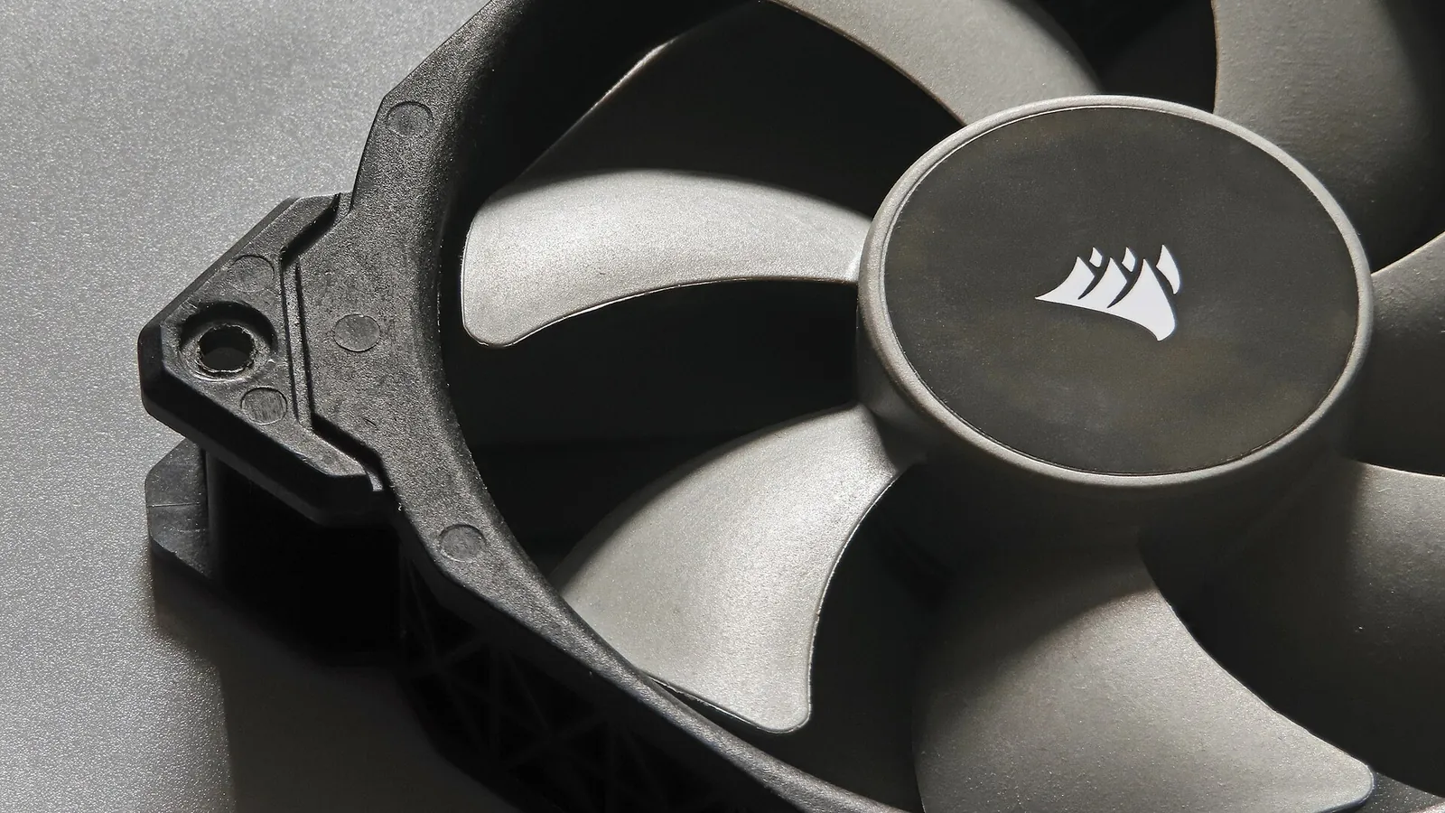
- Cover: Corsair Logo 120mm desktop computer case fan (52504601012) by Eric Chan from Hong Kong, CC BY 2.0, via Wikimedia Commons
- ESP32 Dev Board by Edwiyanto, CC BY-SA 4.0, via Wikimedia Commons
- SRD-05VDC-SL-C 5V one-channel relay module by Suyash Dwivedi, CC BY-SA 4.0, via Wikimedia Commons
- DHT22-Temperatur-Sensor by Ubahnverleih, CC0, via Wikimedia Commons


